Return to Support
[tabby title=”Residential BurnersAF/AFG, AFII, NX, SF/SM, CG4″ icon=”home”]
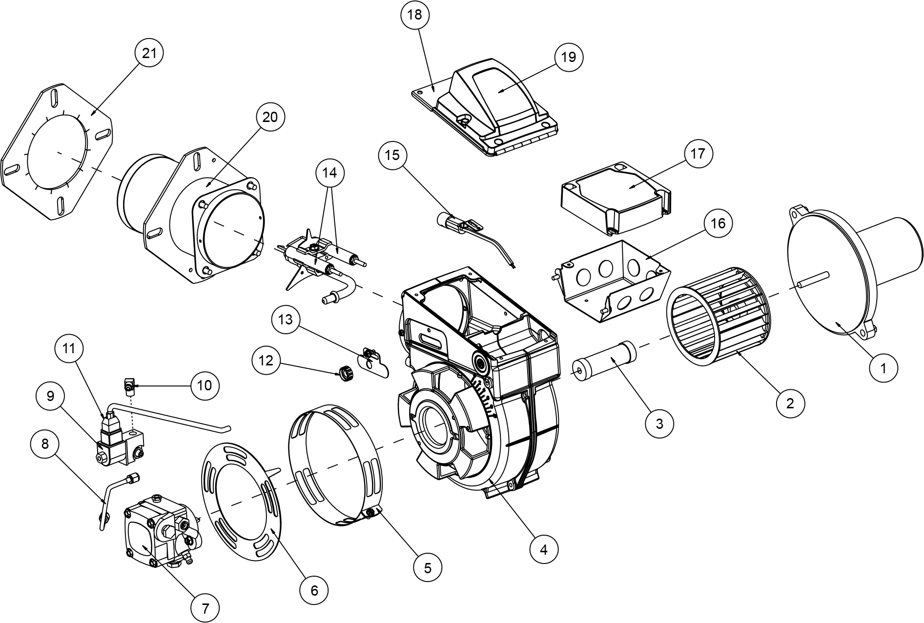
AF/AFG Residential Oil Burner
AF/AFG Replacement Parts

| # | Part No. | Description | AF | AFG |
| 1 | 5624B | Burner Housing Assembly | X | |
| 1 | 5874BKU | Burner Housing Assembly | X | |
| 2 | 3709U | Air Shutter – 4 Slot | X | |
| 2 | 3494U | Air Shutter – 8 Slot | X | |
| 3 | 5151501 | Air Band – 8 Slot | X | X |
| 4 | 21807U | Valve Cordset | X | X |
| 5 | PF20321U | CleanCut Pump | X | X |
| 6 | 5394 | Copper Oil Line – 8” | X | X |
| 7 | 2139 | Hole Plug | X | X |
| 8 | 2454 | Coupling | X | X |
| 9a | 31231U | Air Guide | X | |
| 9b | 31841U | Air Inlet Bell | X | |
| 10a | 2999U | Blower Wheel | X | |
| 10b | 2459U | Blower Wheel | X | |
| 11 | 21805U | PSC Motor | X | X |
| 12 | 5770 | Electrical Box | X | X |
| 13a | 7505A0000U | Interrupted Ignition | X | X |
| 13b | 7505B1500U | Pre-Purge | X | X |
| 13c | 7505P1515U | Pre and Post-Purge | X | X |
| 13d | 7505P1530U | Pre and Post-Purge | X | X |
| 13e | 7505P152MU | Pre and Post-Purge | X | X |
| 14 | 51771U | Igniter & Base Plate 120 VAC | X | X |
| 15 | 51304 | Igniter Gasket Kit | X | |
| 16 | 5880 | Low Firing Rate Baffle | X | |
| 17 | 7006U | Cad Cell Detector | X | X |
AF/AFG Air Tubes, Nozzle Lines, Electrodes, Parts

| # | Part No. | Description | AF | AFG |
| ATC’s | Complete Air Tube Combinations-Refer to Figure 3, Page 5 | X | X | |
| 18a | SL** | Nozzle Line Electrode Assembly (NLEA) – ‘F’ Head Air Tubes | X | X |
| 18b | SL** | Nozzle Line Electrode Assembly (NLEA) – ‘M’ Head Air Tubes | X | |
| 19a | SL** | Tube Only – ‘F’ Head | X | X |
| 19b | SL** | Tube Only – ‘M’ Tube Straight Shroud | X | |
| 19c | SL** | Tube Only – ‘M’ Tube Conic Shroud | X | |
| 20 | 213U | Nozzle Adapter | X | X |
| 21a | 5780 | Electrode Kit – ‘F’ Head up to 9” Tube Length | X | X |
| 21b | 5782 | Electrode Kit – ‘F’ Head 9” + Tube Length | X | X |
| 22 | 5940 | Electrode Kit – ‘M’ Head up to 9” Tube Length | X | |
| 23 | F’ Head | F0 / F3 / F4 / F6 / F12 / F22 / F31 | X | X |
| 24a | 5912U | L1 Head Assembly | X | |
| 24b | 51895U | L2 Head Assembly | X | |
| 24c | 5913U | V1 Head Assembly | X | |
| 25 | 3666U | Splined Nut | X | X |
| 26a | 3493 | Head Adjusting Plate (‘F’, L1, L2 Heads) | X | X |
| 26b | 5941 | Head Adjusting Plate (V1 Head) | X | |
| 27 | 51586 | Heat Shield – ‘F’ Head only | X | X |
**Specify Length
AF/AFG Burner Mounting Flange, Pedestals and Accessories
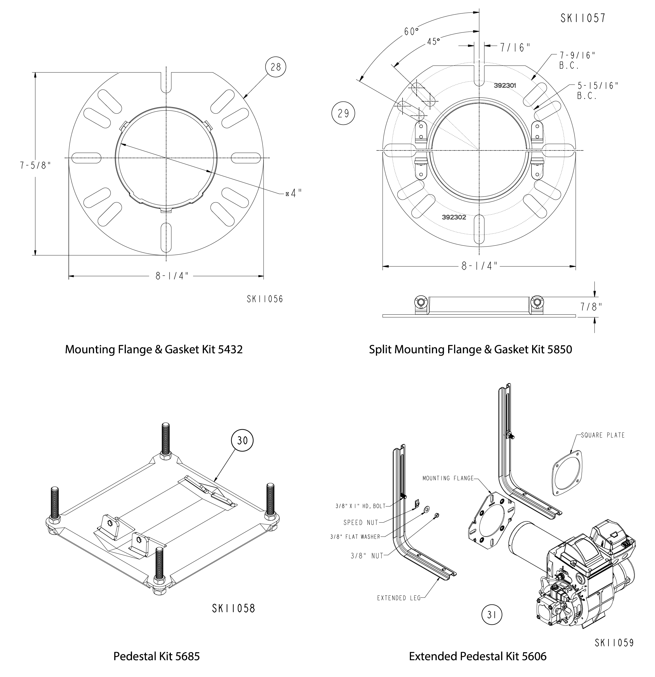
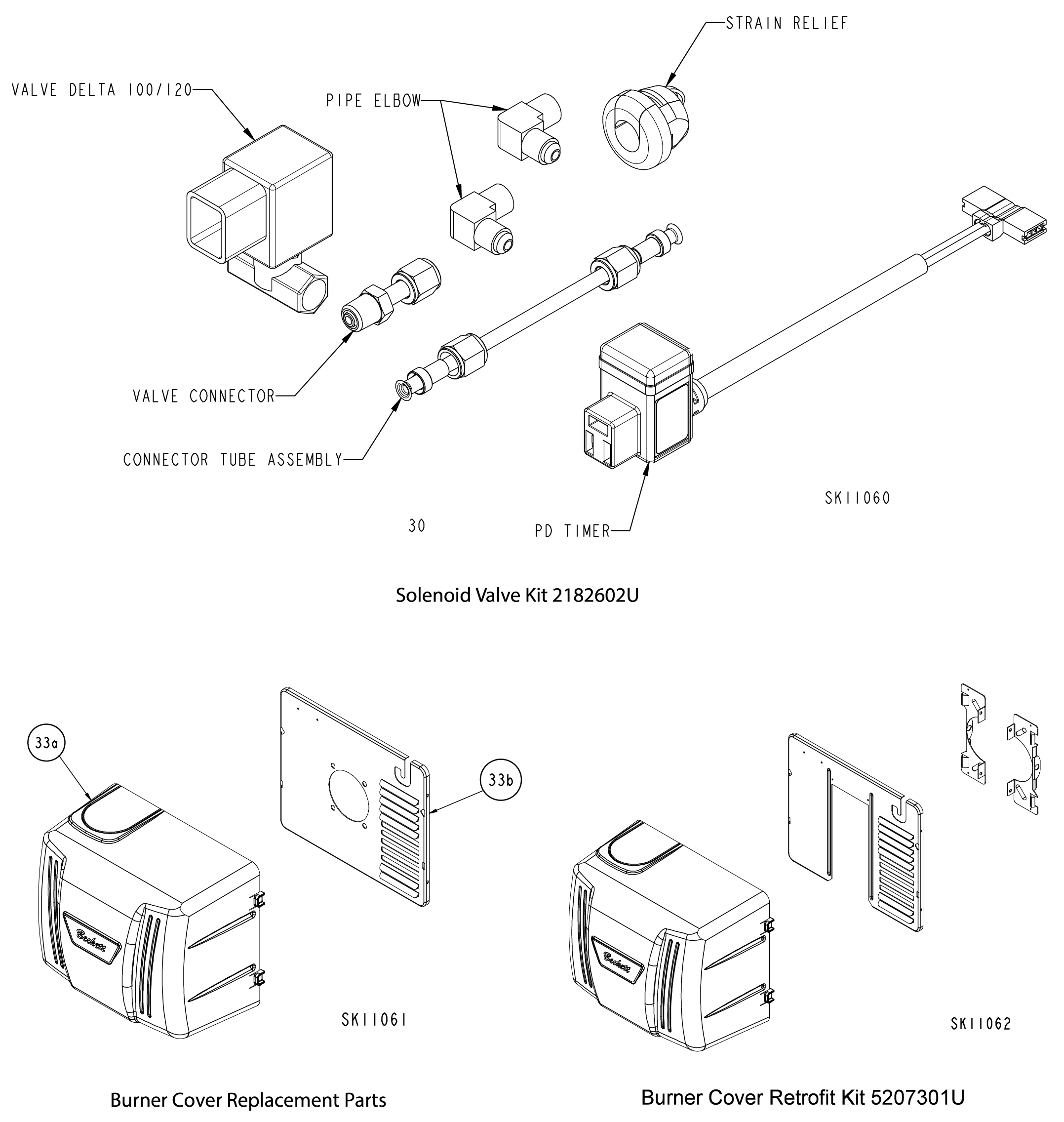
| # | Part No. | Description | AF | AFG |
| NS* | 21887U | PD Timer Delay Cordset for CleanCut Pump | X | X |
| 28 | 5432 | Universal Flange w/ Gasket | X | X |
| NS* | 31653 | Round Flange Gasket Only | X | X |
| NS* | 31802 | Square Flange Gasket Only | X | X |
| 29 | 5850 | Split Flange w/ Gasket | X | X |
| 30 | 5685 | Pedestal Kit | X | X |
| 31 | 5606 | Pedestal Kit – Extended | X | X |
| 32 | 2182602U | Solenoid Valve Kit (Delay) | X | X |
| 33 | 5207301U | Burner Cover Kit | X | X |
| 33a | 52642001U | Burner Cover Kit | X | X |
| 33b | 32109BK | Cover Mounting Plate | X | X |
*Not Shown
AF/AFG Outside Air Kits
| Part No. | Description |
| 51747 | Air Boot Kit Includes: Burner air boot adapter, Vacuum Relief, Inlet air hood |
| 51851U | Outside air adapter for use with 5207301Uburner cover kit |
| 51908U | Air Boot Kit – Mobile Home Applications: Air boot, gaskets, instructions |
AFII Residential Oil Burner
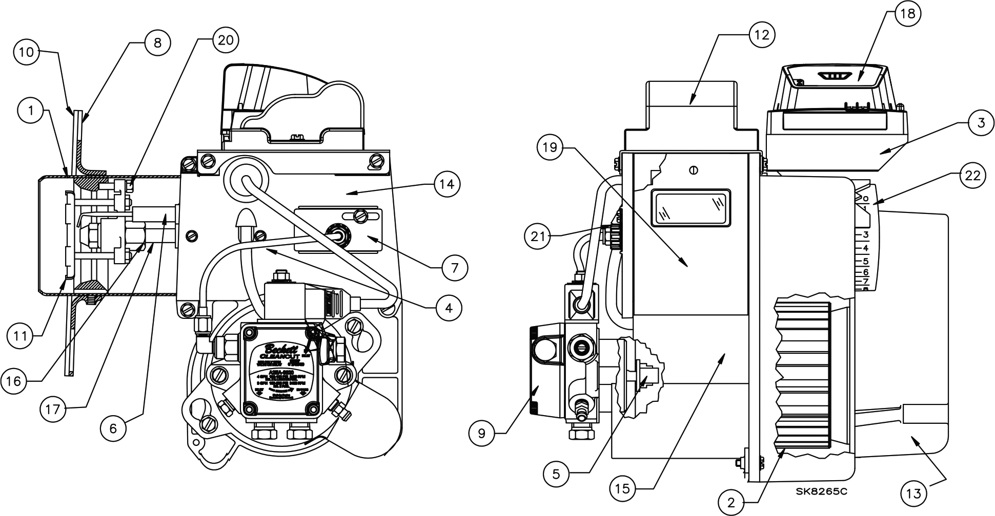
| # | Part No. | Description |
| 1 | Specify when ordering* | Air Tube Combination |
| 2 | Blower Wheel | |
| 21439U | AFII 85 (4¼”) | |
| 21438U | AFII 100 (4½”) | |
| 21438U | AFII 150 (4½”) | |
| 3 | 31613 | Electrical box |
| 4 | 5394 | Connector tube, 8″ Copper |
| 5 | 21437U | Coupling, Motor to Pump |
| 6 | Electrodes | |
| 51484U | HLX Heads | |
| 51670U | FBX Heads | |
| 7 | Escutcheon Plate | |
| 31623 | AFII Blank | |
| 3162302 | AFII 140psi | |
| 8 | 51480 | Flange Kit, (adjustment 3½” ID w/gasket) |
| 9 | 2184404U | Fuel Pump: CleanCut |
| 10 | 31658 | Gasket, flange |
| 11 | Head | |
| Specify when ordering* | FBX: FB0, FB3 or FB6 | |
| 51671U | HLX: AF2 6 Slot Head | |
| 51672U | AF2 9 Slot Head | |
| 51685 | Head insulator Kit (FB0, 3, 4, 6 only) | |
| 12 | 51805U | Igniter, electronic |
| 13 | 51485 | Inlet air scoop, plastic, sound insulated |
| 14 | Housing Assembly | |
| 51584U | AFII 85 & 100 | |
| 51476U | AFII 150 | |
| 15 | 21444U | Motor: 1/7HP, 3450RPM, 115v/60Hz |
| 16 | 213 | Nozzle adapter |
| 17 | Specify when ordering* | Nozzle Line Electrode Head Assembly |
| 18 | 7505A | Replaces R7184A – Interrupted Ignition |
| 7505B | Replaces R7184B – Pre-time** | |
| 7505P | Replaces R7184P – Pre- and Post-time** | |
| 19 | 51424U | Rear Access Door |
| 20 | 51483 | Stop Screw Replacement Kit |
| 21 | 3666 | Splined Nut |
| 22 | 51758 | Dial, Air Adjustment (UL approved) |
| (not shown) | Consult Burner Settings guide (OEM Spec Guide) for recommendations. See Nozzle Product Page for part numbers. |
Nozzle |
NX Residential Oil Burner
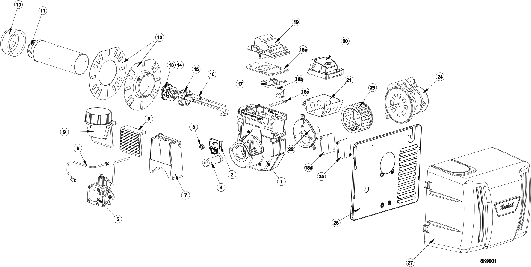
| # | Part No. | Description |
| 1 | Specify when ordering** | Housing |
| 2 | 52000U | Head/Air adjustment mechanism assembly |
| 3 | 3666 | Splined nut |
| 4 | 2454 | Coupling |
| 5 | 2184404U | CleanCut Fuel Pump, (Includes Mounting Screws ¼-20 x ⅞” – Part #4189) |
| 6 | 51127 | Connector tube assembly, 11” |
| 7 | 1010U | Inlet air box |
| 8 | 1013U | Inlet air louvers |
| 9 | 1014U | Inlet Air Adapter, Outside air kit |
| 10 | Specify when ordering** | Heat Shield (per specification) |
| 11 12 |
Specify when ordering** | Air tube combination (Includes Screws, Air Tube mounting #8 x ⅜ – Part #4396) |
| 13 | 51785U | Retention head assembly, 6 -slot* |
| 14 | 51815U | Retention head assembly, 9 -slot* |
| 15 | Specify when ordering** | Nozzle Line Electrode and Head Assembly, with window |
| 16 | 51811U | Electrode insulator kit |
| 17 | 32058U | Spring, igniter prop |
| 18 | 51942U | Gasket, Igniter kit |
| 18a | Gasket, Igniter baseplate | |
| 18b | Gasket, Wiring hinge | |
| 18c | Gasket, Igniter baseplate hinge | |
| 18d | Gasket, Rear access door | |
| 19 | 51771U | Igniter, electronic |
| 20 | 7505A | Replaces R7184A – Interrupted Ignition |
| 7505B | Replaces R7184B – Pre-Time** | |
| 7505P | Replaces R7184P – Pre and Post-Time** | |
| 21 | 5770 | Electrical Box |
| 22 | 101101U | Air guide |
| 23 | 2999U | Blower wheel |
| 24 | 21805U | PSC Motor, (Requires mounting screw ¼-20 x ⅞ – Part #4189) |
| 25 | 32119U | Door, Rear Access |
| 26 | 32103U | Mounting Plate, Burner Cover |
| 27 | 52064xxU** | Cover, Burner |
| 51801U | Universal Adjustable Flange Kit. Includes 32086 Gasket. | |
| (not shown) | Consult Burner Settings guide (OEM Spec Guide) for recommendations. See Nozzle Product Page for part numbers. |
Nozzle |
SF/SM Residential Oil Burner
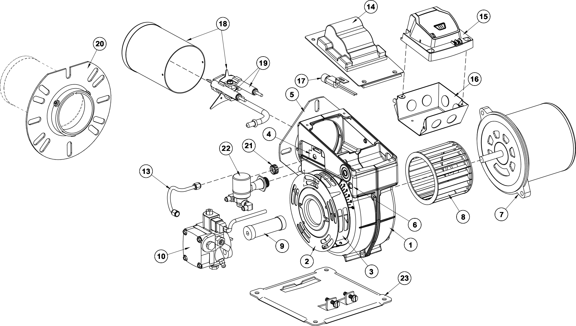
| # | Part No. | Description |
| 1 | – | Burner Housing Assembly with Inlet Bell |
| 2 | 3215 | Air shutter, 10 Slot |
| 3 | 3819 | Bulk Air Band, 10 Slot |
| 4 | 3493 | Nozzle-line Escutcheon Plate |
| 5 | Specify when ordering** | Unit Flange or |
| 3399 | Square Plate | |
| (not shown) | 3416 | Air Tube Gasket |
| 6 | 2139 | Hole Plug – Wiring Box |
| 7 | 2900U | Drive Motor, 1/5HP (SM Models) |
| 2364U | Drive Motor, ¼HP (SF Models) | |
| 8 | 2383U | Blower Wheel (6¼” X 3 7/16“) |
| 9 | 2433 | Flexible Coupling (Fits 5/16″ pump shaft) |
| 10 | Fuel Units SF only | |
| 2591U | Single-Stage ‘A’ | |
| 21188U | Two-Stage ‘B’ | |
| Fuel Units SM only | ||
| 2184404U | CleanCut | |
| 2460 | Single-Stage ‘A’ | |
| (not shown) | 2256 | Pump outlet fitting |
| (not shown) | 482 | Pump holding screws |
| 13 | 5394 | Connector tube assembly, pump to nozzle line |
| 14 | 51824U | Igniter and Base Plate |
| 14 | 2289U | Ignition Transformer (10,000 V/23mA) |
| 15 | 7505A/7575A | Replaces R7184A – Interrupted Ignition |
| 7505B/7575B | Replaces R7184B – Pre-time | |
| 7505P/7575P | Replaces R7184P – Pre- and Post-time (7575P used for all SM burners) |
|
| 16 | 5770 | Electrical Box |
| 17 | 7006U | Cad Cell Detector |
| 18 | Specify when ordering** | Air Tube Combination |
| 19 | 5780 | Electrode Kit – F Head up to 9” |
| 5782 | Electrode Kit – F Head over 9” | |
| 20 | 5432 | Universal Flange w/ Gasket |
| 3616 | Gasket Only | |
| 21 | 3666 | Splined Nut |
| 22 | 2182602U | Blocking Oil Solenoid Valve |
| 23 | 5685 | Base Pedestal Kit |
| (not shown) | Consult Burner Settings guide (OEM Spec Guide) for recommendations. See Nozzle Product Page for part numbers. |
Nozzle |
**Contact your Beckett Representative for part number and pricing.
CG4 Residential Gas Burner
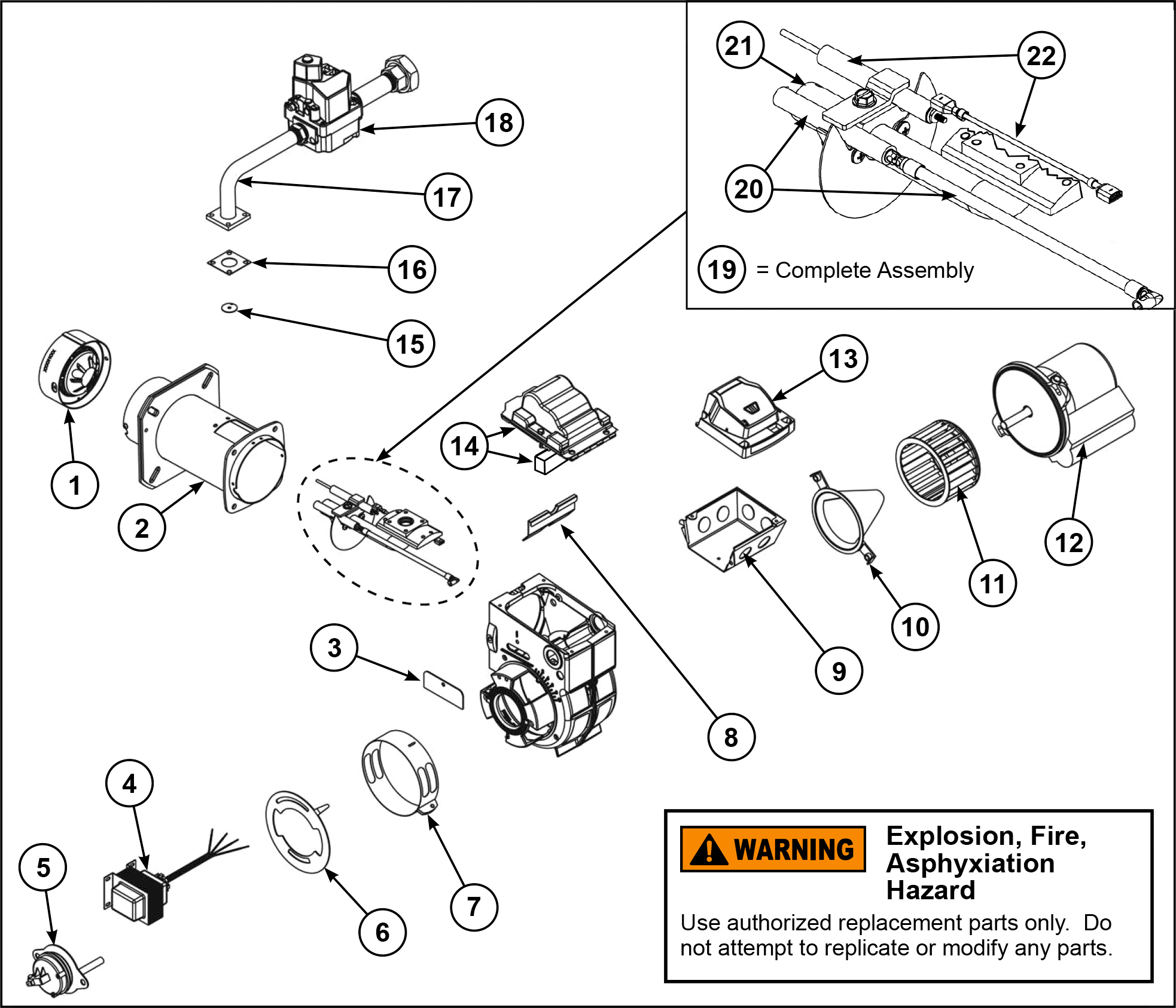
| # | Part No. | Description |
| 1 | F3GU, F4GU, or F6GU | Head |
| 2 | Specify when ordering* | Air Tube Assembly |
| 3 | 32282U | Cover Plate |
| 4 | 52310U | Transformer |
| 5 | 52264U | Air Proving Switch & Cover Assembly |
| 6 | 3709U | Shutter (4-slot) |
| 7 | 5151502 | Air band (Blank) |
| 5151504 | Air Band (4-Slot) | |
| 8 | 5880 | Air Baffle |
| 9 | 5770 | Electrical Box |
| 10 | 31231U | Air Guide |
| 11 | 2999U | Blower Wheel |
| 12 | 21805U | Motor |
| 13 | 7590D0001U | GeniSys Primary Control |
| 14 | 7474U | Igniter & Gasket |
| 15 | F3GNATU | Natural Gas Orifice pack (F3G) |
| F4GNATU | Natural Gas Orifice pack (F4G) | |
| F6GNATU | Natural Gas Orifice pack (F6G) | |
| F3GLPU | LP Orifice pack (F3G) | |
| F4GLPU | LP Orifice pack (F4G) | |
| F6GLPU | LP Orifice pack (F6G) | |
| 16 | 33021001U | Gasket, Manifold |
| 17 | 52296001U | Gas Manifold Assembly |
| 18 | 22470U | Gas Valve |
| 19 | Specify when ordering* | Gas Gun Assembly |
| 20 | 5784U | Electrode/Wire Assembly |
| 21 | F3GNOZU | Nozzle (F3G) |
| F4GNOZU | Nozzle (F4G) | |
| F6GNOZU | Nozzle (F6G) | |
| 22 | 7590FRU | Flame Rod/Wire Assembly |
*Contact your Beckett representative for part number and pricing.
ADC, SDC” icon=”bolt”]
ADC 12v Oil Burner

| # | Part No. | Description |
| 1 | N/A | DC Motor |
| 2 | 2999U | Blower Wheel |
| 3 | 2140501 | Coupling |
| 4 | 31231U | Air Guide |
| 5 | 5874BKU | Burner Housing – Black |
| 6 | 5151501 | Air Band |
| 7 | 3709 | Air Shutter – 4 Slot |
| 3494 | Air Shutter – 8 Slot | |
| 8 | 21807 | Cord set |
| 9 | 2184402U | Pump (CleanCut) |
| 10 | 21877U | Valve Stem |
| 11 | 21754U | 12 Volt Coil |
| 12 | 5394 | 8″ Copper Tubing |
| 13 | 3666 | Escutcheon Plate Spline Nut |
| 14 | 3493 | Escutcheon Plate |
| 15 | 578731 | Electrode Kit over 3⅝” |
| 16 | 7492/7006U | Cad Cell Detector |
| 17 | 51411 | Igniter Gasket Kit |
| 18 | 5770 | 4X4 Wiring Box Kit |
| 19 | 7556x-xxxxU* | Control Kit |
| 20 | 5218301U | Igniter Assembly with baseplate |
| 21 | 5218309 | Igniter only |
| 22 | Specify when ordering | Air Tube Assembly |
| 23 | Specify when ordering | Flange Mounting Gasket |
| 24 | 52145U | Motor Kit with Blower Wheel and Coupling |
| (not shown) | 578730 | Tune-up Kit for 30 & 35 Air Tube Lengths |
| (not shown) | Consult Burner Settings guide (OEM Spec Guide) for recommendations. See Nozzle Product Page for part numbers. |
Nozzle |
*’X‘s indicate timing options. Contact Beckett for available part numbers.
SDC 12v Oil Burner
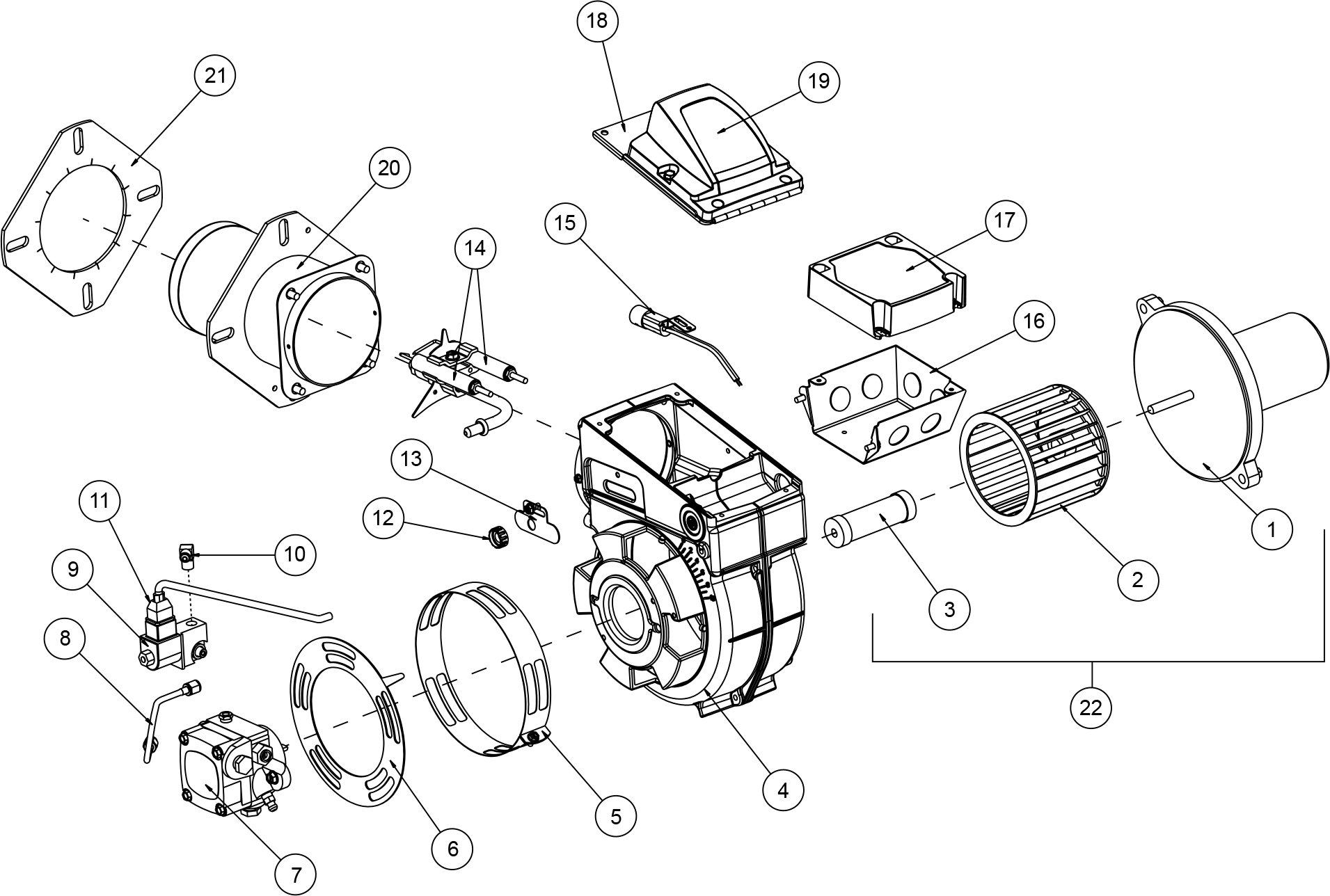
| # | Part No. | Description |
| 1 | N/A | DC Motor |
| 2 | 2383AU | Blower Wheel (6¼”) |
| 3 | 2154101 | Coupling |
| 4 | 5348B | Burner Housing |
| 5 | 3819A | Air Band, 10 slot |
| 6 | 3215 | Air Shutter, 10 slot |
| 7 | Specify when ordering | Pump |
| 8 | 5394 | Connector Tube Assembly |
| 9 | Specify when ordering | Oil Valve |
| 10 | 2256 | Brass Elbow |
| 11 | 21807 | Cord Set, Valve |
| 12 | 3666 | Splined Nut |
| 13 | 3493 | Escutcheon Plate |
| 14 | 578731 | Electrode Kit over 3⅝” |
| 15 | 7006U | Cad Cell Detector |
| 16 | 5770 | 4X4 Wiring Box |
| 17 | 7556X-XXXXU* | Control Kit |
| 18 | 5218303U | Igniter Assembly With Base Plate |
| 19 | 5218309U | Igniter only |
| 20 | Specify when ordering | Air Tube Assembly |
| 21 | Specify when ordering | Flange Mounting Gasket |
| 22 | 52146U | Motor Kit with Blower Wheel and Coupling |
| (not shown) | 578730 | Tune-up Kit for 30 and 35 Air Tube lengths |
| (not shown) | Consult Burner Settings guide (OEM Spec Guide) for recommendations. See Nozzle Product Page for part numbers. |
Nozzle |
*’X‘s indicate timing options. Contact Beckett for available part numbers.
ADC 24v Oil Burner
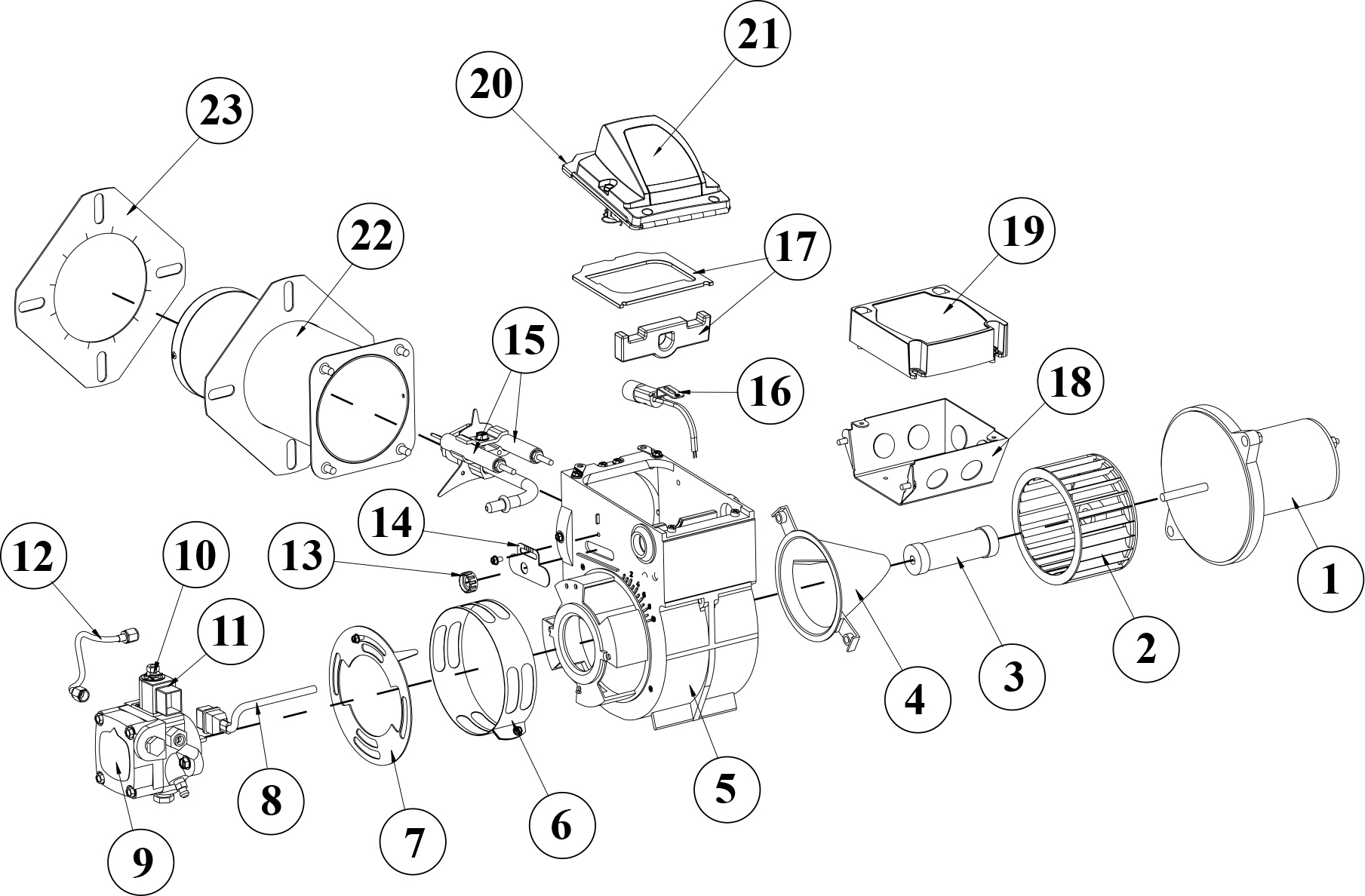
| # | Part No. | Description |
| 1 | 21773U | DC Motor |
| 2 | 2999U | Blower Wheel |
| 3 | 2140501 | Coupling |
| 4 | 31231U | Air Guide |
| 5 | 5874BKU | Burner Housing – Black |
| 6 | 5151501 | Air Band |
| 7 | 3709 | Air Shutter – 4 Slot |
| 3494 | Air Shutter – 8 Slot | |
| 8 | 21807 | Cord set |
| 9 | 2184407U | Pump (CleanCut) |
| 10 | 21877U | Valve Stem |
| 11 | 22245U | 12 Volt Coil |
| 12 | 5394 | 8″ Copper Tubing |
| 13 | 3666 | Escutcheon Plate Spline Nut |
| 14 | 3493 | Escutcheon Plate |
| 15 | 578731 | Electrode Kit over 3⅝” |
| 16 | 7492/7006U | Cad Cell Detector |
| 17 | 51411 | Igniter Gasket Kit |
| 18 | 5770 | 4X4 Wiring Box Kit |
| 19 | 7559x-xxxxU* | Control Kit |
| 20 | 205218501U | Igniter Assembly with baseplate |
| 21 | 5218503U | Igniter only |
| 22 | Specify when ordering | Air Tube Assembly |
| 23 | Specify when ordering | Flange Mounting Gasket |
| (not shown) | 578730 | Tune-up Kit for 30 & 35 Air Tube Lengths |
| (not shown) | Consult Burner Settings guide (OEM Spec Guide) for recommendations. See Nozzle Product Page for part numbers. |
Nozzle |
*’X‘s indicate timing options. Contact Beckett for available part numbers.
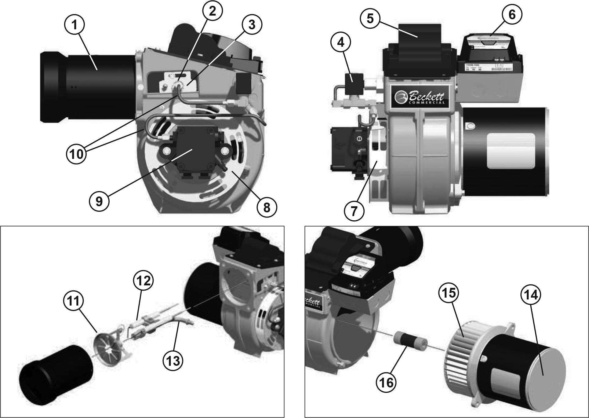
SDC 24v Oil Burner
| # | Part No. | Description |
| 1 | 22190U | DC Motor |
| 2 | 2383U | Blower Wheel (6¼”) |
| 3 | 2154101 | Coupling |
| 4 | – | Burner Housing |
| 5 | 3819A | Air Band, 10 slot |
| 6 | 3215 | Air Shutter, 10 slot |
| 7 | Specify when ordering | Pump |
| 8 | 5394 | Connector Tube Assembly |
| 9 | 22246 | Oil Valve |
| 10 | 2256 | Brass Elbow |
| 11 | 21807 | Cord Set, Valve |
| 12 | 3666 | Splined Nut |
| 13 | 3493 | Escutcheon Plate |
| 14 | 578731 | Electrode Kit over 3⅝” |
| 15 | 7006U | Cad Cell Detector |
| 16 | 5770 | 4X4 Wiring Box |
| 17 | 7559X-XXXXU* | Control Kit |
| 18 | 5218502U | Igniter Assembly With Base Plate |
| 19 | 5218503U | Igniter only |
| 20 | Specify when ordering | Air Tube Assembly |
| 21 | Specify when ordering | Flange Mounting Gasket |
| (not shown) | Tune-up Kit for 30 and 35 Air Tube lengths | 578730 |
| (not shown) | Consult Burner Settings guide (OEM Spec Guide) for recommendations. See Nozzle Product Page for part numbers. |
Nozzle |
*’X‘s indicate timing options. Contact Beckett for available part numbers.
CF Series, CG Series” icon=”industry”]
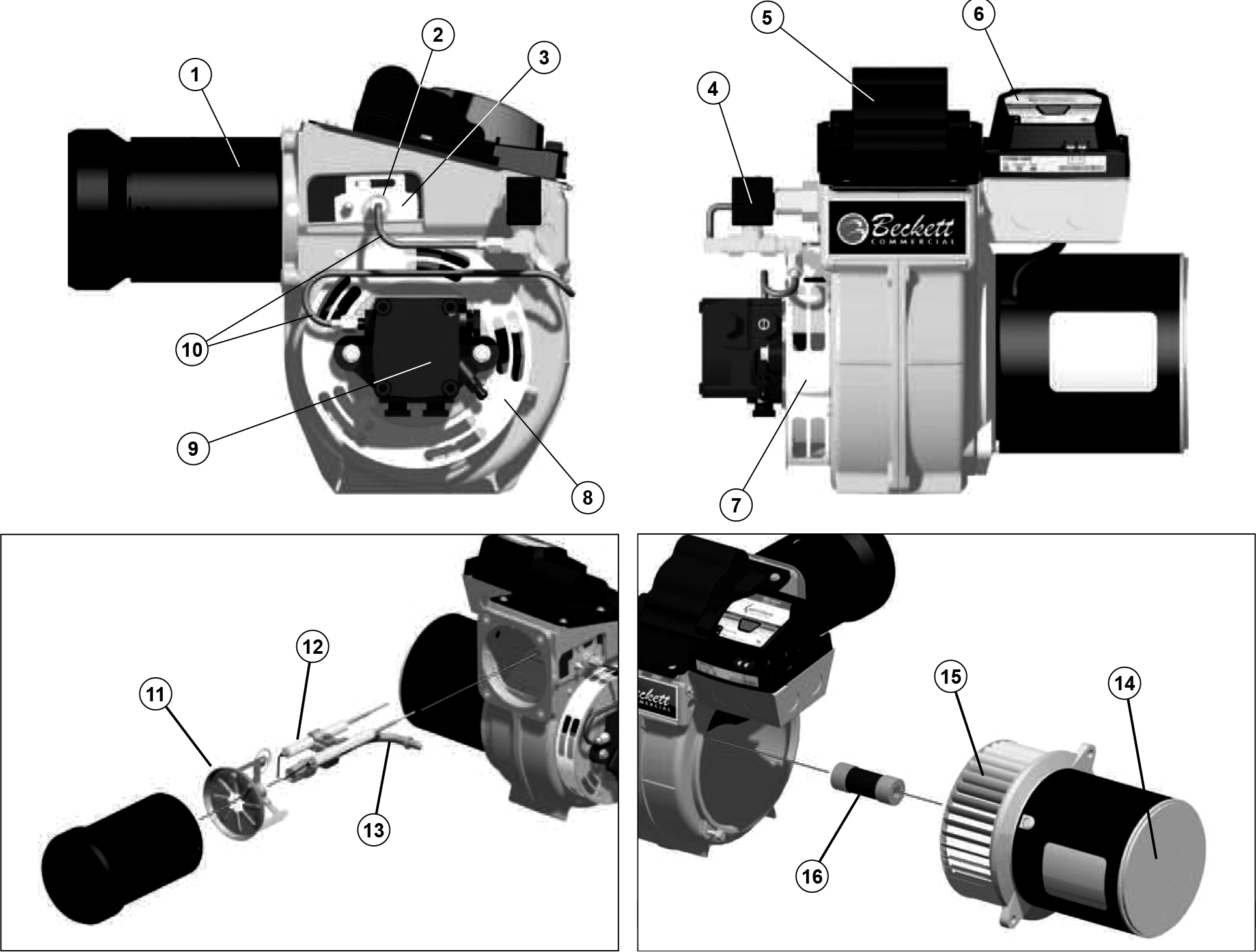
CF375 Commercial Oil Burner
Note: CF500/800 shown, CF375 is similar.
| # | Part No. | Description |
| 1 | See Figure 3 in burner manual | Air Tube |
| 2 | 3666 | Spline Nut |
| 3 | 5721 | Adjusting plate assembly |
| 4 | 2182602U | Blocking Oil Solenoid Valve |
| 5 | 51771U | Igniter |
| 6 | Specify when ordering | Control |
| 7 | 3492 | Air Band |
| 8 | 3709 | Air Shutter |
| 9 | See Table 2 in burner manual | Fuel Pump |
| 10 | Specify lengths when ordering | Fuel lines |
| 11 | 5913 | Head Assembly – KY (Tube A) |
| 51820 | Head Assembly – KZ (Tube B) | |
| 12 | Refer to Figure 6 in burner manual | Electrode Assembly |
| 13 | Refer to Figure 6 in burner manual | Nozzle Line Assembly |
| 14 | 21805U | Motor – 1/7HP PSC |
| 15 | 21837U | Blower Wheel |
| 16 | 2454 | Coupling |
| (not shown) | 5432 | Flange Kit – non-pressure fired |
| 51311 | Flange Kit – pressure fired |
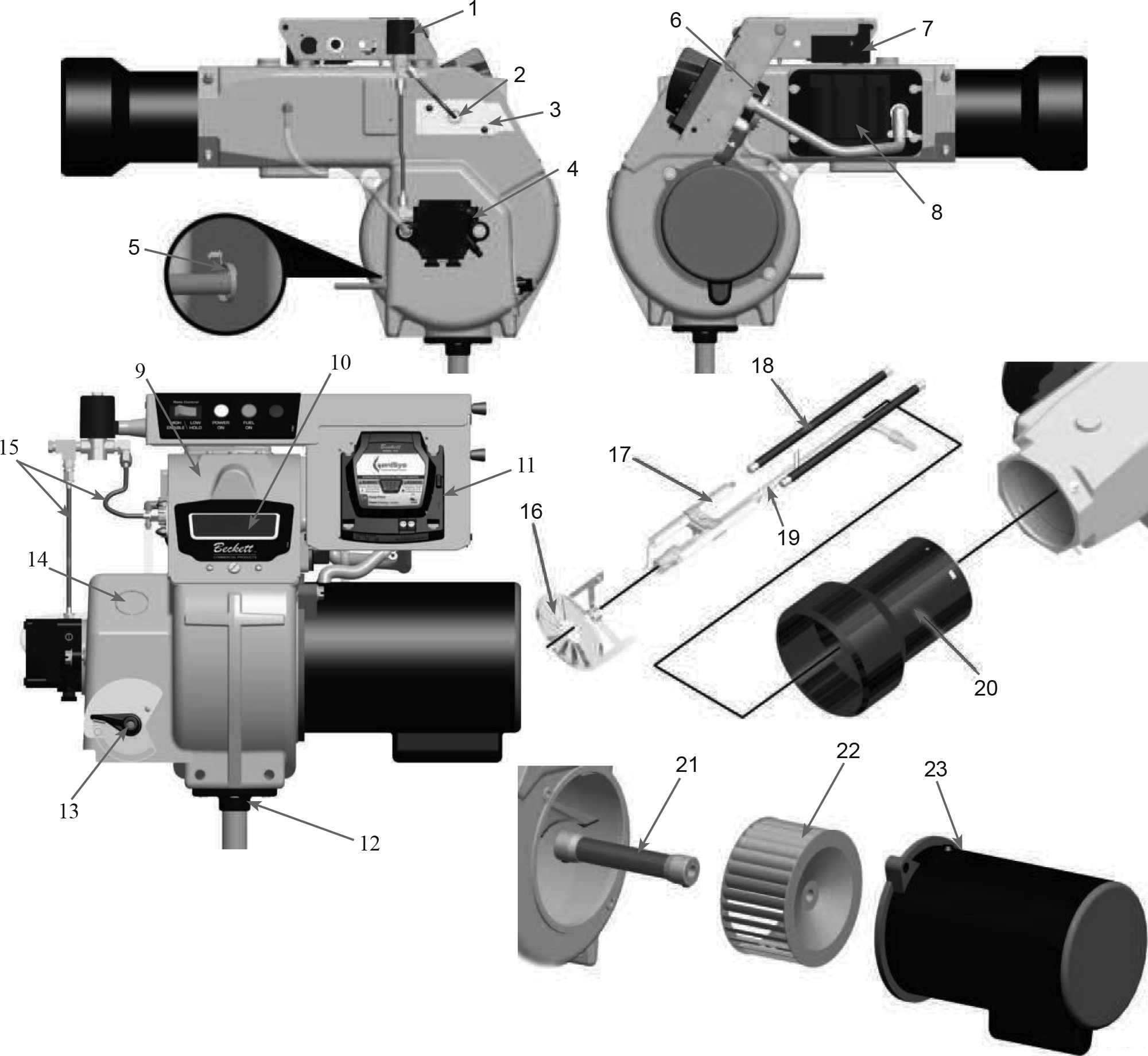
CF500/CF800 Commercial Oil Burners
| # | Part No. | Description |
| 1 | Specify when ordering | Air Tube |
| 2 | 3666 | Spline Nut |
| 3 | 51286U | Adjusting plate assembly |
| 4 | 2182602U | Blocking Oil Solenoid Valve |
| 5 | 51824U | Igniter |
| 6 | Specify when ordering | Control |
| 7 | 3819 | Air Band |
| 8 | 3215 | Air Shutter |
| 9 | Specify when ordering | Fuel Pump |
| 10 | Specify lengths when ordering | Fuel lines |
| 11 | Head Assembly | |
| CF500 – KK | 51401U | |
| CF800 – KH (Tube A) | 51252P | |
| CF800 – KJ (Tube B) | 51302P | |
| CF500 & CF800 with CF140KZ air tube | 51820U | |
| 12 | Specify when ordering | Electrode Assembly |
| 13 | Specify when ordering | Nozzle Line Assembly |
| 14 | 21341U | Motor – 1/3HP PSC |
| 15 | Blower Wheel | |
| CF500 – 5-19/32” x 2-13/32” | 21448U | |
| CF800 – 6-5/16” x 2-3/8” | 21339U | |
| 16 | 2433 | Coupling |
| 17 | See Figure 13 in burner manual | Flange Kit |
| (not shown) | – | Pedestal Kit |
| (not shown) | Consult Burner Settings guide (OEM Spec Guide) for recommendations. See Nozzle Product Page for part numbers. |
Nozzle |
CF1000 Commercial Oil Burner
| # | Part No. | Description |
| 1 | 21789U | Oil Valve – Mounted on Junction Box |
| 2 | 3666 | Knurled Nut – All Models |
| 3 | 51213U | Adjusting Plate Assembly CF10-2300 Kit |
| 4 | 21313U | Fuel Pump B2TA-8245 |
| 5 | 4339 | Damper Spring – All models |
| 6 | 22181U | Air Proving Switch 2″ W.C. |
| 7 | 21295U | Timer Nozzle Valve Delay |
| 8 | 51214 | Transformer 12,000 volt |
| 9 | 5994U | Rear cover door assembly w/Cast aluminum door* |
| 5201301U | Rear cover door assembly w/Stamped sheet-metal door* | |
| 10 | 31346 | Sight Glass All Models |
| 11 | Specify when ordering | Control |
| 12 | 51193 | Pedestal kit All models |
| 13 | 5985BK | Damper indicator All models |
| 14 | 32439U | Coupling Hole Plug Use with threaded hole |
| 15 | Specify length when ordering | Fuel lines |
| 16 | 5978P | Head assembly CF1000 combustion |
| 17 | 51212 | Electrode assembly – All models |
| 18 | 5990082 | Ignition leads 8¼” long |
| 5990116 | Ignition leads 11¾” long | |
| 5990152 | Ignition leads 15¼” long | |
| 5990192 | Ignition leads 19¼” long | |
| 19 | Refer to Figure 5 in burner manual | Nozzle line assembly |
| 20 | Refer to Figure 2 in burner manual | Air tube |
| 21 | 21290 | Coupling B pump |
| 22 | 21268U | Blower wheel CF1000 5.59″ x 3.09″ |
| 23 | 21401U | Motor 120/208-230V single phase |
| 21638U | Motor 208/230-460V three phase | |
| (not shown) | 752804 | Motor Relay 120V Single phase |
| 7300 | Motor Relay 208V Single phase | |
| 2194301 | Motor Relay Three Phase | |
| (not shown) | Refer to Figure 18 in burner manual | Adjustable flange |
| (not shown) | Consult Burner Settings guide (OEM Spec Guide) for recommendations. See Nozzle Product Page for part numbers. |
Nozzle |
*These doors are NOT interchangeable. Please specify when ordering.
CF1400/CF2300 Commercial Oil Burners
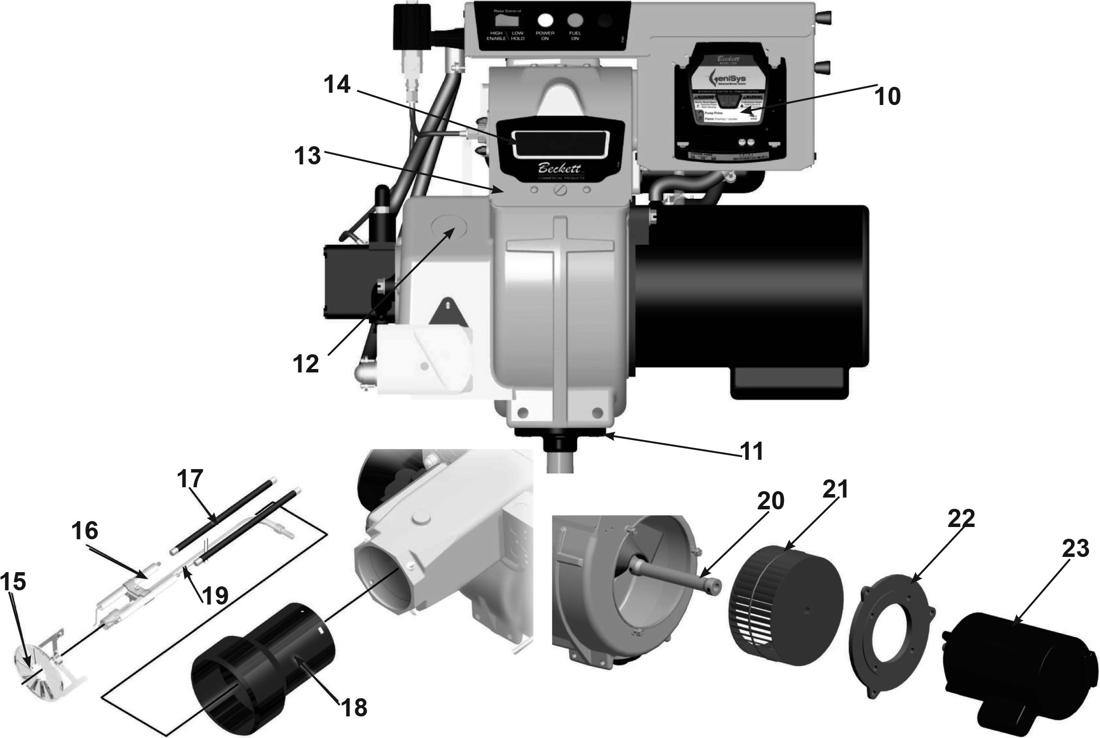
| # | CF1400 Part No. | CF2300 Part No. | Description |
| 1 | 21789U | 21789U | Oil Valve Mounted on Junction Box |
| 2 | 3666 | 3666 | Knurled Nut – All models |
| 3 | 51213U | 51213U | Adjusting plate assembly w/ cast aluminum door |
| 5201701U | 5201701U | Adjusting plate assembly w/ stamped sheet-metal door | |
| 4 | 21259U | – | Fuel pump B2TA-8851 |
| – | 21487U | Fuel pump B2TA-8852 | |
| 5 | 750601U | 750601U | Damper motor 2-stage |
| 6 | Specify length when ordering | Fuel lines | |
| 7 | 22181U | 22181U | Air Proving Switch 2” W.C. |
| 8 | 21295U | 21295U | Timer Nozzle Valve Delay |
| 9 | 51214 | 51214 | Transformer 12,000 volt |
| 10 | Specify when ordering | Control | |
| 11 | 51193 | 51193 | Pedestal kit All models |
| 12 | 32439U | 32439U | Coupling hole plug use with threaded hole |
| 13 | 5994U | 51204U | Rear cover door assembly w/ cast aluminum door* |
| 5201301U | 5201302U | Rear cover door assembly w/ stamped sheet-metal door* | |
| 14 | 31346 | 31346 | Sight glass – All models |
| 15 | 5978 | 51203 | Head assembly |
| 16 | 51212 | 51212 | Electrode assembly – All models |
| 17 | 5990082 | 5990082 | Ignition leads 8¼” long |
| 5990116 | 5990116 | Ignition leads 11¾” long | |
| 5990152 | 5990152 | Ignition leads 15¼” long | |
| 5990192 | 5990192 | Ignition leads 19¼” long | |
| 18 | Refer to Figure 4 in burner manual | Air tube | |
| 19 | Refer to Figure 5 in burner manual | Nozzle line assembly | |
| 20 | 21290 | 21549 | Coupling B Pump |
| 21 | 21268U | – | Blower wheel CF1400 – 5.59″ x 3.09″ |
| – | 21267U | Blower wheel CF2300 – 6.75″ x 3.13″ | |
| 22 | N/A | 31347U | Motor Mounting Flange |
| 23 | 21401U | 21402U | Motor 120/208-230 single phase |
| 21638U | 21499U | Motor 208-230/460 three phase | |
| (not shown) | 752804 | 752804 | Motor Relay 120V single phase |
| 7300 | 7300 | Motor Relay 208V single phase | |
| 2194301 | 2194301 | Motor Relay three phase | |
| (not shown) | See Figure 18 in burner manual | Adjustable Flange | |
| (not shown) | Consult Burner Settings guide (OEM Spec Guide) for recommendations. See Nozzle Product Page for part numbers. |
Nozzle | |
*These doors are NOT interchangeable. Please specify when ordering.
CF2500/CF3500 Commercial Oil Burners
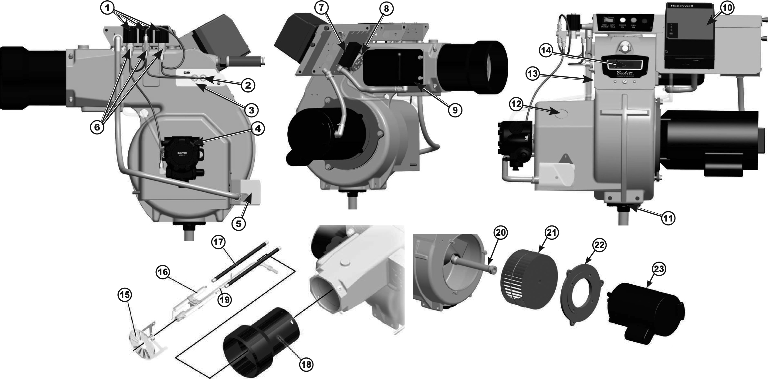
| # | CF2500 Part No. | CF3500 Part No. | Description |
| 1 | 21789U | Oil Valve – Mounted on Junction Box | |
| 2 | 3666 | Knurled Nut – All Models | |
| 3 | 5201703U | Adjusting Plate Assembly w/ Stamped Sheet Metal Door | |
| 4 | 21529U | Fuel Pump J4PA-C10506 | |
| 5 | 750601U | Damper Motor – 2 Stage | |
| 6 | Specify length when ordering | Fuel Lines | |
| 7 | 21295U | Timer – Nozzle Valve Delay | |
| 8 | 22182U | Air Proving Switch – 4″ W.C. | |
| 9 | 51214 | Transformer 12,000 Volts | |
| 10 | Refer to UL label for Model Numbers | Control | |
| 11 | 31346 | Pedestal Kit – All Models | |
| 12 | 32439U | Coupling Hole Plug – Use with Threaded Holes | |
| 13 | 5994U | 51204U | Rear Cover Door Assembly w/ Cast Aluminum Door |
| 5201301U | 5201302U | Rear Cover Door Assembly w/ Stamped Sheet Metal Door | |
| 14 | 31346 | Sight Glass – All Models | |
| 15 | 51475P | Head Assembly KP/KM | |
| – | 51637P | Head Assembly KR | |
| 16 | 51212 | Electrode Assembly – All Models | |
| 17 | 5990092 | Ignition Leads 9¼” long | |
| 5990104 | Ignition Leads 10½” long | ||
| 5990126 | Ignition Leads 12¾” long | ||
| 5990162 | Ignition Leads 16¼” long | ||
| 5990202 | Ignition Leads 20¼” long | ||
| 18 | Refer to Figure 2 in burner manual | Air Tube | |
| 19 | Refer to Figure 5 in burner manual | Nozzle Line Assembly | |
| 20 | 21514 | Coupling H Pump | |
| 21 | 21528U | Blower Wheel 8.25″ x 4.18″ | |
| 22 | 31449U | Mounting Flange | |
| 23 | 21527U | Motor 120/208-230 Single Phase | |
| 21547U | Motor 208-230/460 Three Phase | ||
| 21733U | Motor 575 Three Phase | ||
| (not shown) | 752804 | Motor Relay 120V Single Phase | |
| 7300 | Motor Relay 208V Single Phase | ||
| 2194301 | Motor Relay Three Phase | ||
| (not shown) | Refer to Figure 19 in burner manual | Adjustable Flange | |
| (not shown) | Consult Burner Settings guide (OEM Spec Guide) for recommendations. See Nozzle Product Page for part numbers. |
Nozzle | |
CG10 Commercial Gas Burner
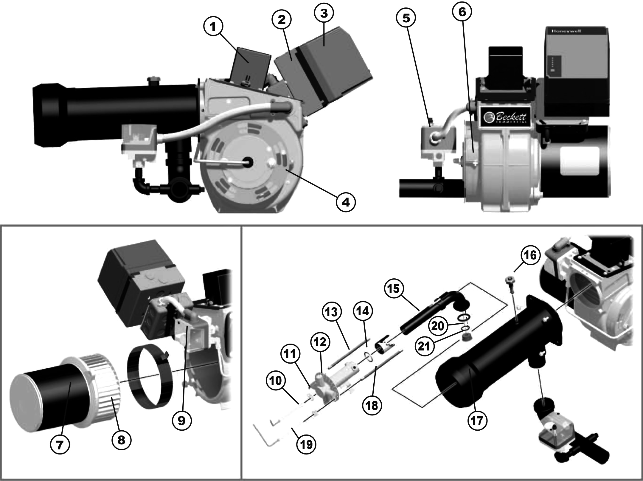
| # | Part No. | Description |
| 1 | 7503U | Ignition Transformer |
| 2 | Refer to the UL Label for controller model number. | Control Subbase |
| 3 | Refer to the UL Label for controller model number. | Primary Control |
| 4 | 3215U | Shutter |
| 5 | 2190903U | High Gas Pressure Switch |
| 6 | 3819A | Air Band |
| 7 | 21341U | Motor – 120V |
| 21654U | Motor – 220V | |
| 8 | 21448U | Blower Wheel – CG10 |
| 21339U | Blower Wheel – CG10A or CG10B | |
| 9 | 2190901U | Air Proving Switch |
| 10 | Specify application when ordering | Electrode Set |
| 11 | 3236501U | Spring Clamps (4 in package) |
| 12 | Specify application when ordering | Head |
| 13 | 5990130U | Cable, Ignition Electrode |
| 14 | 32264U | O-ring set (2 in package) |
| 15 | 5193201U | Gas Tube Assembly |
| 16 | 5193401U | Jacking Screw |
| 17 | Specify application when ordering | Air Tube |
| 18 | 5990280U | Cable, Flame Rod (if used) |
| 19 | 2191301U | Flame Rod (if used) |
| (not shown) | 7247U | UV Scanner |
| 20 | 3226409U | Restrictor O-ring (LP Only) |
| 21 | See Table 3 in burner manual | Propane Restrictor (LP Only) |
CG10-24 Commercial Gas Burner
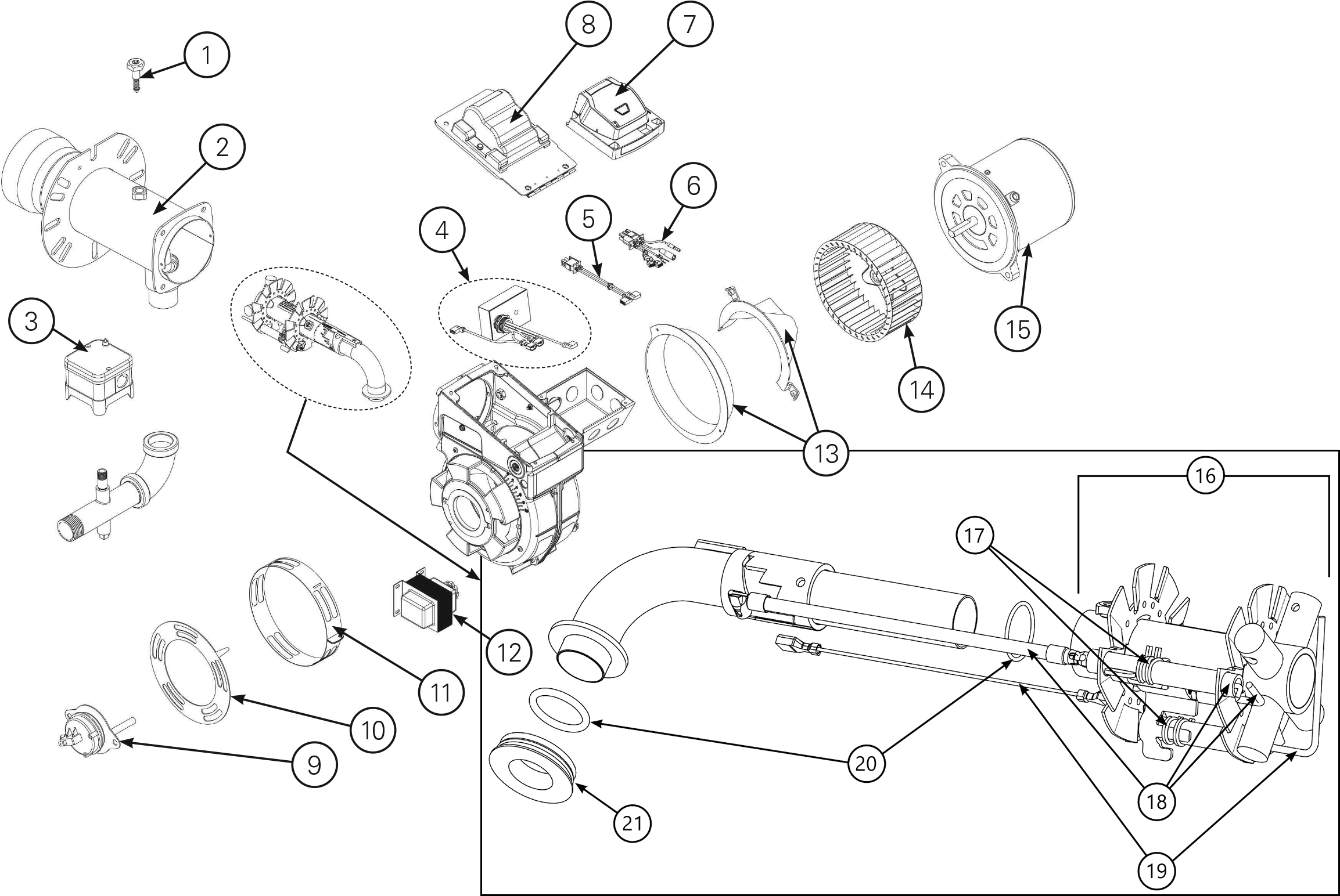
| # | Part No. | Description |
| 1 | 5193401U | Jacking Screw |
| 2 | Specify application when ordering | Air Tube |
| 3 | 52259-001U | Low Gas Pressure Switch |
| 52259-002U | High Gas Pressure Switch | |
| 4 | 52402001U | Valve Timer |
| 5 | 52268001U | Wire Assembly – Air Proving Switch |
| 6 | 52401001U | Wire Assembly – 6 pin |
| 7 | 7590C0001U | Primary Control |
| 8 | 7474002U | Ignition Transformer |
| 9 | 52264002U | Air Proving Switch Assembly |
| 10 | 3215U | Shutter |
| 11 | 5151503 | Air Band |
| 12 | 52310002U | 24V Transformer |
| 13 | 189U | Air Inlet – Air Guide (300-600 MBH) |
| 178U | Air Inlet – Air Guide (600-1,000 MBH) | |
| 32336U | Air Inlet – Inlet Sleeve | |
| 14 | 21448U | Blower Wheel – CG10 (300-600 MBH) |
| 21339U | Blower Wheel – CG10A or B (600-1,200 MBH) | |
| 15 | 21341U | Motor 120V |
| 16 | 101U | Head with Electrode 10.1 |
| 101SU | Head with Electrode 10.1S | |
| 102U | Head with Electrode 10.2 | |
| 102SU | Head with Electrode 10.2S | |
| 103U | Head with Electrode 10.3 | |
| 103SU | Head with Electrode 10.3S | |
| 104U | Head with Electrode 10.4 | |
| 104SU | Head with Electrode 10.4S | |
| 105U | Head with Electrode 10.5 | |
| 105SU | Head with Electrode 10.5S | |
| 106U | Head with Electrode 10.6 | |
| 106SU | Head with Electrode 10.6S | |
| 17 | 3236501U | Spring Clamps (4-pack) |
| 18 | 22225U | Electrode Set with Cable 10.4 – 10.6 |
| 2191201U | Electrode Set with Cable 10.1 – 10.3 | |
| 2191205U | Electrode Set with Cable 10.1S – 10.6S | |
| 19 | 2191305U | Flame Rod with Cable |
| 20 | 3226401U | O-ring Set (2-piece) |
| 21 | See Table 6 in burner manual | Propane Restrictor (LP Only) |
| (not shown) | 2193410U | Solenoid Gas Valve 24V, 1″ NPT |
| (not shown) | 2193411U | Solenoid Gas Valve 24V, ¾” NPT |
| (not shown) | 32990001U | 2 Stage Gas Safety Valve 24V, 1″ NPT |
| (not shown) | 2192901CU | Regulator Maxitrol ¾” NPT |
| (not shown) | 2192902DU | Regulator Maxitrol 1″ NPT |
CG15/CG25/CG50 Commercial Gas Burners
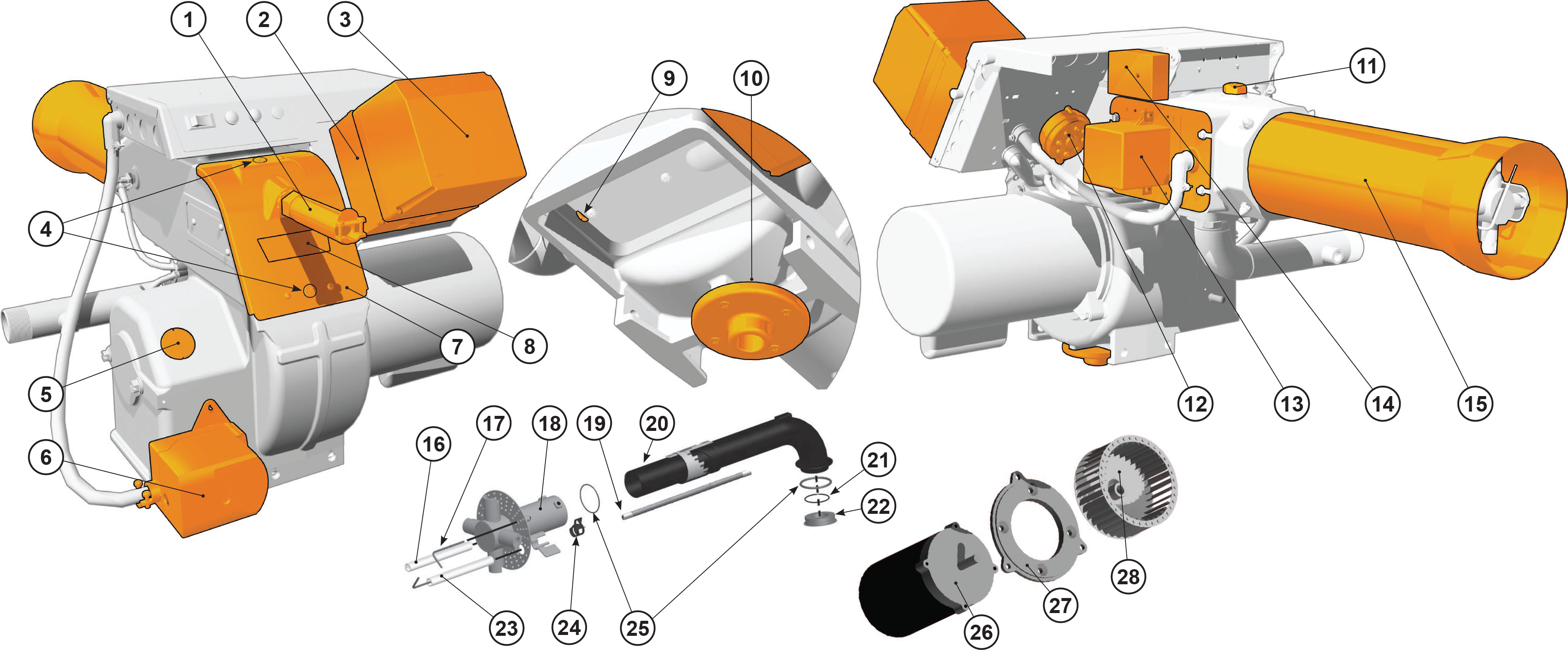
| # | CG15 Part No. | CG25 Part No. | CG50 Part No. | Description |
| 1 | 7247U | UV Sensor | ||
| 2 | Refer to UL label for Model Numbers | Control Subbase | ||
| 3 | Refer to UL label for Model Numbers | Control | ||
| 4 | 32444U | Spring Latch (Dzus Fastener) | ||
| 5 | 32439U | Coupling Hole Plug | ||
| 6 | 750601U | Damper Motor Lo/Hi | ||
| 750603U | Damper Motor Modulation | |||
| 7 | 5201303U | 5201304U | Rear Access Door For UV* | |
| 5201301U | 5201302U | Rear Access Door For Flame Rod* | ||
| 8 | 31346U | Sight Glass** | ||
| 9 | 32294U | Nylon Bushing | ||
| 10 | 51193 | Pedestal Kit – All Models | ||
| 11 | 5193402U | 5193403U | Jacking Screw Assembly | |
| 12 | 22181U | 22182U | Air Proving Switch | |
| 13 | 7503U | Ignition Transformer | ||
| 14 | 21295U | Timer (if used) | ||
| 15 | Specify model when ordering | Air Tube | ||
| 16 | 3231 | Ceramic | ||
| 17 | 2191106U | Ground Electrode | ||
| 18 | Specify model when ordering | Head, Welded Assembly | ||
| 19 | 5990184U | Cable, Ignition Electrode | ||
| 20 | 5193202BKU | 5193203BKU | 5193204BKU | Gas Tube, Welded Assembly |
| 21 | 3226401U | 3226402U | 3226403U | Restrictor O-ring (LP Only) |
| 22 | See Table 4 in burner manual | Propane Restrictor (LP Only) | ||
| 23 | 2191206U | 2191207U | 2191208U | Ignition Electrode |
| 24 | 4474U | Clamp | ||
| 25 | 3226402U | 3226403U | 3226404U | O-ring Set (2 included) |
| 26 | 21401U | 21402U | 21527U | Motor 115-208-203V |
| 21638U | 21499U | 21547U | Motor 208-230/380-460V | |
| 21735U | 21734U | 21733U | Motor 575V | |
| 27 | N/A | 31347U | 31449U | Mounting Flange |
| 28 | 21268U | 21267U | 21528U | Blower Wheel |
| (not shown) | 2190902U | 2229401U | Low Gas Pressure Switch | |
| (not shown) | 2190903U | 2229402U | High Gas Pressure Switch | |
*Includes Sight Glass, Label, Gaskets and Fasteners.
**Includes Beckett Label and Window Gasket.

