
Fusible Inline Valves
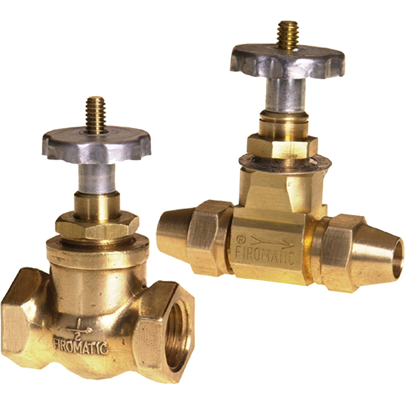
For inline installation. Heavy duty high quality Brass design. Flare and Threaded designs in ¼” through 1″ sizes.
| Part No. | Description |
| 12109 | ¼” FPT X ¼” FPT † |
| 12110 | ⅜” FPT X ⅜” FPT † |
| 12111 | ⅜” FPT inlet X ¼” MPT outlet † |
| 12112 | ¾” FPT X ¾” FPT |
| 12113 | 1″ FPT X 1″ FPT |
| 12130 | ½” FPT X ½” FPT † |
| 12140 | ⅜”ODF X ⅜” ODF with flare nuts † |
| 12150 | ½” ODF X ½” ODF with flare nuts † |
† These valves conform to cULus MH 46634 and are listed as Manual Valves in the US and Canada and are required by NFPA 31 code and CSA B139-15 code.
Fusible Burner (Angle) Valves
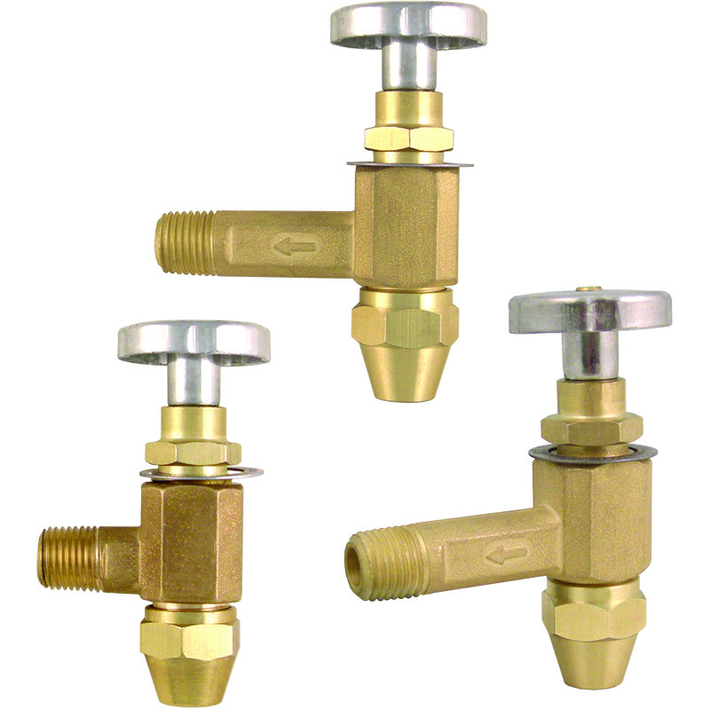
Used at Burner as secondary protection. Heavy duty high quality Brass design. ⅜” and ½” Flare tubing fittings and ¼” NPT to burner. Three lengths available to handle most installation situations.
| Part No. | Description |
| 12210 | ⅜” ODF inlet X ¼” MPT outlet (¾” long) † |
| 12230 | ⅜” ODF inlet X ¼” MPT outlet (1¼” long) † |
| 12250 | ½” ODF inlet X ¼” MPT outlet (1¼” long) † |
| 12270 | ⅜” ODF inlet X ¼” MPT outlet (2″ long) † |
| 12280 | ½” ODF inlet X ¼” MPT outlet (2″ long) † |
† These valves conform to cULus MH 46634 and are listed as Manual Valves in the US and Canada and are required by NFPA 31 code and CSA B139-15 code.
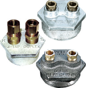
Fusible Tank Valves
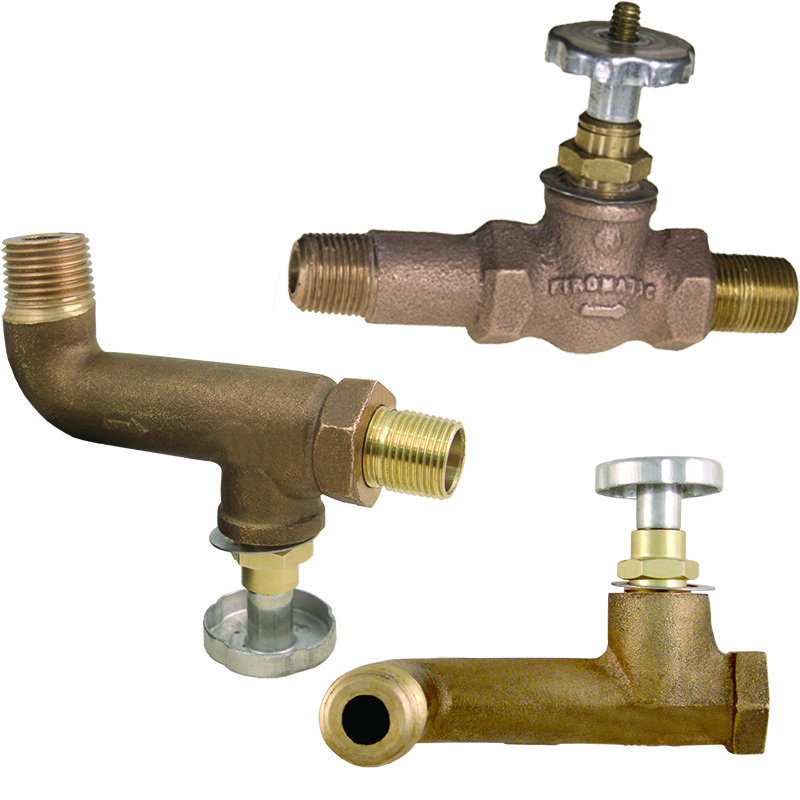
Designed to be installed at the ½” NPT bottom outlet tapping of most residential tanks. Heavy duty Bronze casting. Male nipple included.
| Part No. | Description |
| 12320 | ⅜” MPT inlet X ⅜” MPT Nipple outlet † |
| 12340 | ½” MPT inlet X ⅜” MPT Nipple outlet 90° † |
| 12350 | ½” MPT inlet X ⅜” MPT Nipple outlet 90° side † |
† These valves conform to cULus MH 46634 and are listed as Manual Valves in the US and Canada and are required by NFPA 31 code and CSA B139-15 code.
Lever Valves
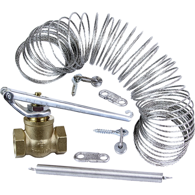
The Lever Valve offers added protection in certain situations. It is sometimes used at the Tank and held open by a spring loaded flexible wire in which fusible links are set. If the temperature at the link reaches standard temperature (165°F), the links will pull apart and the valve will immediately close, stopping the flow of oil. (All accessories shown below are included).
Accessories furnished with each each Lever Valve: take-up spring, coil of braided wire, two fusible links (set at 165°F) and two Pulleys. 212°F links available (purchased separately).
| Part No. | Description |
| 12521 | ⅜” FPT X ⅜” FPT Lever Valve – Complete Kit |
| 12522 | ⅜” FPT X ⅜” FPT Lever Valve – Valve Only |
| 12523 | ½” FPT X ½” FPT Lever Valve – Complete Kit |
| 12524 | ½” FPT X ½” FPT Lever Valve – Valve Only |
| 12525 | ¾” FPT X ¾” FPT Lever Valve – Complete Kit |
| 12526 | ¾” FPT X ¾” FPT Lever Valve – Valve Only |
| 12541 | Fuse Link – 165°F |
| 12543 | Fuse Link – 212°F |
| 12547 | Wire Coil – Lever Valve |
| 12548 | Pulley Assembly – Lever Valve |
| 12549 | Spring Take-Up – Lever Valve |
Check Valves
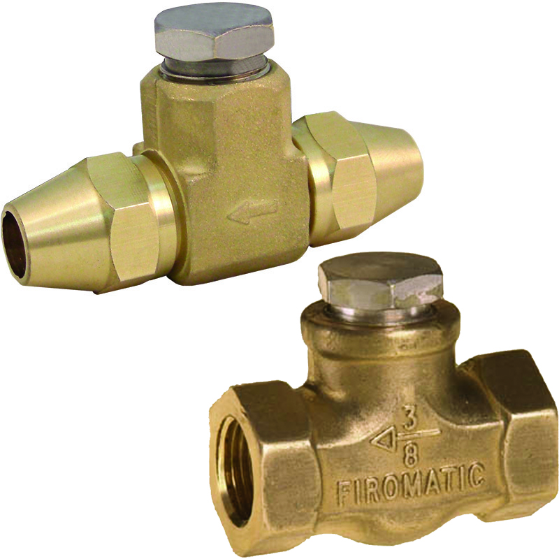
Used to prevent ‘back-flow’ in fuel oil lines. Uses Viton® equivalent seal.
| Part No. | Description |
| 12409 | ¼” FPT X ¼” FPT (B50HCV) |
| 12410 | ⅜” FPT X ⅜”FPT (B100HCV) |
| 12420 | ⅜” ODF X ⅜” ODF with flare nuts (B105HCV) |
| 12430 | ½” FPT X ½” FPT (B200HCV) |
| 12440 | ½” ODF X ½” ODF with flare nuts (B205HCV) |
Thermal Switches
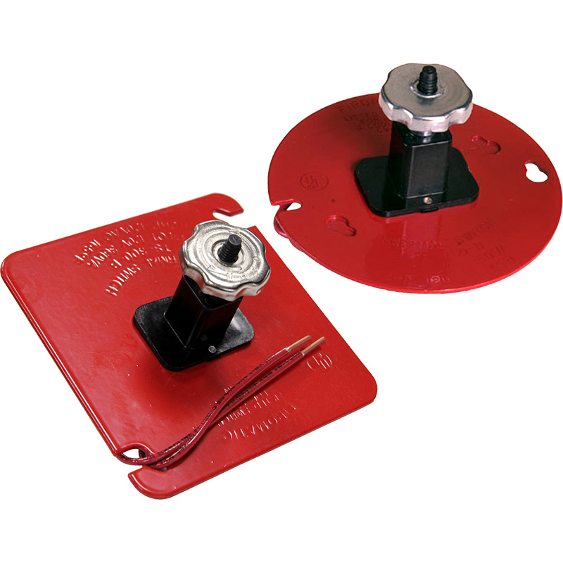
Thermal switches – A safety device which provides added protection to fuel burner installations. It is a thermally operated switch installed in the electrical power line to the burner. It is normally set at 165 degrees F and removes power if the ambient temperature reaches this point. The burner then shuts off immediately. The thermal switch is usually positioned on the ceiling, close to the burner. It SHOULD NOT be used manually to start and stop the burner. When properly installed, there are no exposed electrical wires or contacts, before or after firing – this is important. The fusible element is the hand wheel of the switch – after it ‘fires’, simply replace the hand wheel to restore the switch.
Contact ratings:
- Pilot 120 volts, 60 Hz, 360VA.
- ½ Horsepower, 12 volts, 60Hz.
| Part No. | Description |
| 12501 | U.L. Switch for 4″ X 4″ Square Junction Box |
| 12527 | U.L. Switch for 4″ Round/Octagon Junction Box |